AGV Handling Robot Commonly Uses Sensor Principles and Their Advantages and Disadvantages, Application Introduction
_%E7%94%BB%E6%9D%BF%201.avif)
Ⅰ. LiDAR
(1) Uncover how LiDAR locks onto high-speed targets in real time!
LiDAR is a sensor system that detects target information by emitting a laser beam. Its core principle is: emit laser to the target and receive the reflected signal, determine the target distance by calculating the laser round-trip time; at the same time, the device rotates at high speed for 360-degree scanning, collects dense point cloud data (a collection of coordinates on the surface of the object), and constructs a 2D/3D digital model of the environment in real time. The system can accurately measure the position, speed, shape and many other parameters of the target, and is widely used in the fields of autonomous driving, mapping and so on.
1. Point cloud data is a collection of all object surface points detected by the LiDAR within the scanning range. Each point contains two types of core information:
① Reflectivity characteristics
Value range: 0-255
Diffusely reflecting objects: 0-150 (corresponding to reflectivity 0%-100%)
Reflective objects: 151-255 (e.g. metal, glass)
Note: When the object is <2m away from the Mid-360 radar, the reflectivity error is large, and only the total reflection/diffuse reflection type can be judged.
② Spatial coordinates
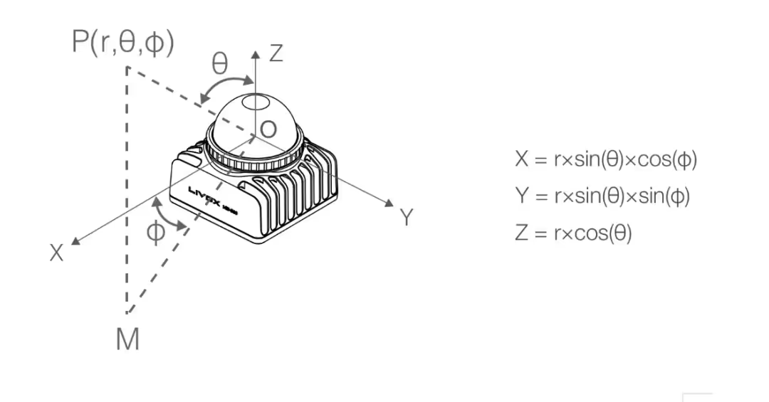
Type of coordinate system: Cartesian coordinates (x,y,z) or spherical coordinates (r,θ,φ).
When detection is effective: Output the true coordinate value.
When detection is invalid (no object/over-range > 100m):
Cartesian coordinates: (0,0,0)
Spherical coordinates: (0,θ,φ) (retain current scanning angle information)
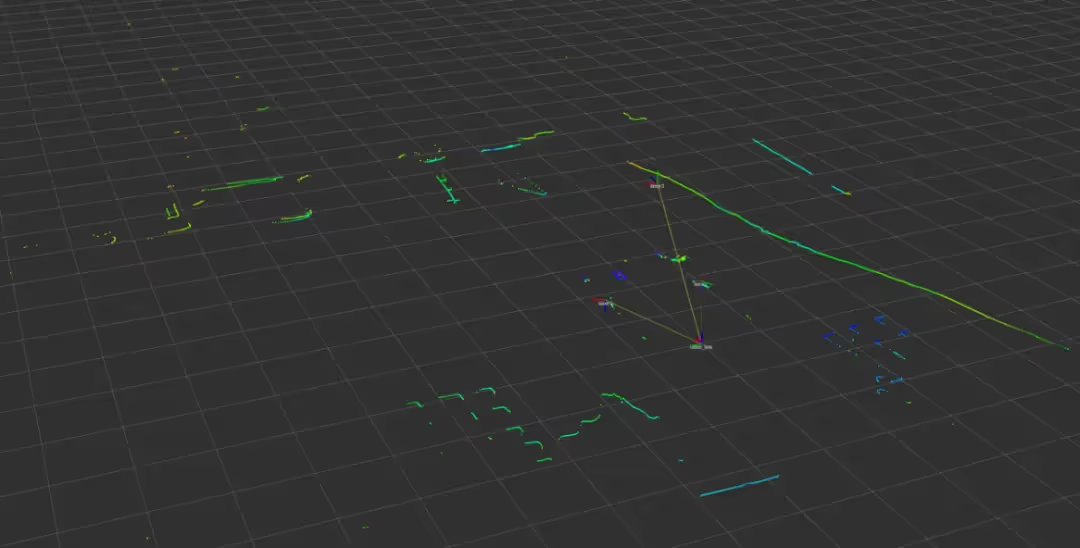
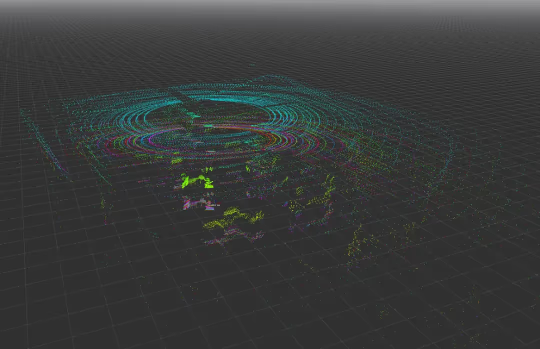
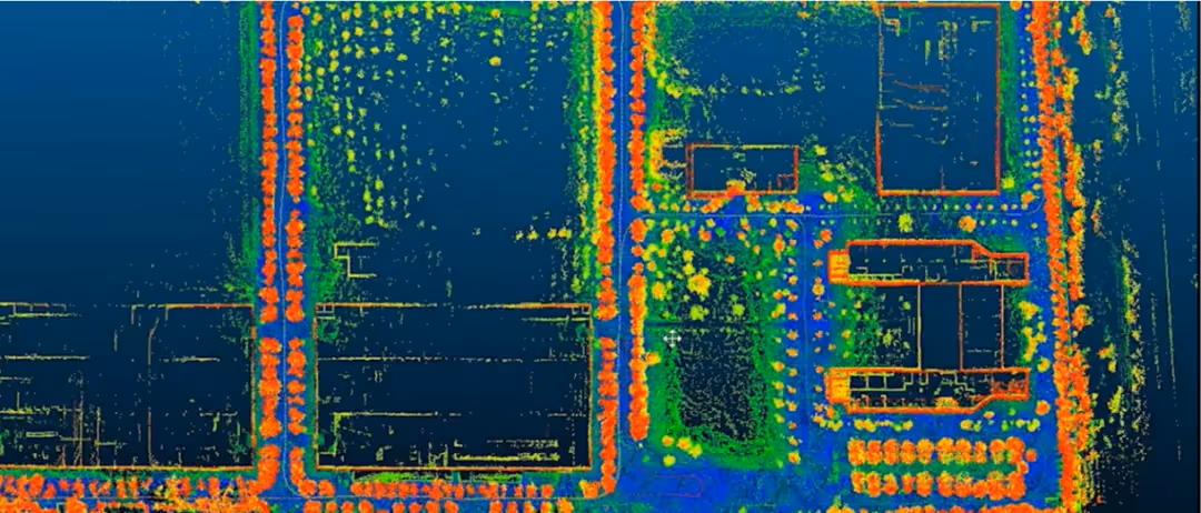
2. LiDAR can be divided into single-line LiDAR and multi-line LiDAR according to the classification of the number of lines. Single-line LiDAR refers to the laser source issued by the beam is a single line of radar, access to the 2D planar scanning map; multi-line LiDAR refers to the simultaneous emission and reception of multiple beams of laser rotating ranging radar, the market is currently 4 line, 8 line, 16 line, 32 line, 64 line, and 128 line of points. Multi-line LiDAR can recognise the height information of an object and obtain a 3D scan of the surrounding environment. A visualisation of the 2D and 3D point cloud is shown in the figure.
(2) Why does navigation always guess which way you want to go?
Laser navigation is a commonly used navigation method in AGV systems. According to its navigation principle, AGVs can walk freely in the navigation area and locate precisely; within the navigation range, the travelling path of the vehicle can be changed at any time according to the actual requirements, which can give full play to the flexibility of the AGVs and improve the production efficiency. Many systems need to be carried out under the existing site conditions, which will be particularly suitable for laser navigation AGV systems.
1. The core principles of laser navigation can be summarised in two main principles:
① Map construction (learning the environment for the first time)
When the AGV starts up for the first time, it scans its surroundings from all sides with LiDAR, just like ‘scanning a room with a laser pointer’.
Using SLAM technology (Autonomous Localisation + Mapping), it records the position of fixed objects such as walls and equipment to create a digital map of the environment.
②Real-time positioning (position finding when navigating)
While the AGV is moving, the LiDAR continuously scans and acquires a ‘snapshot’ point cloud of the surrounding environment in real time.
The real-time data is compared with the stored map (similar to the ‘Find the Difference Game’), and the algorithm calculates the current precise position and orientation of the AGV.

2. Laser navigation features:
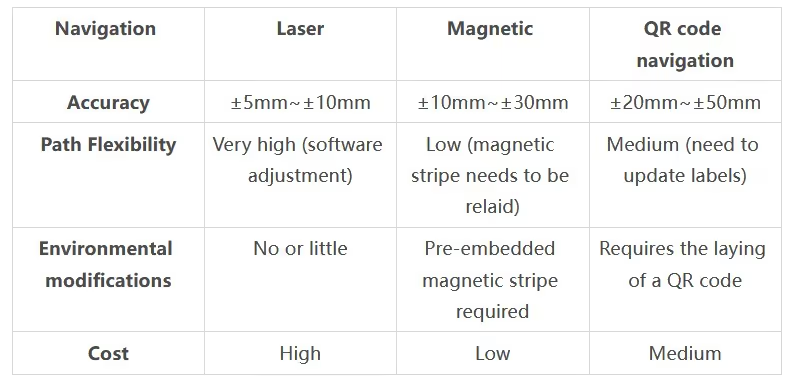
High-precision positioning and navigation, suitable for scenes with strict requirements for accuracy, such as stacking pick and place goods; strong environmental adaptability, complex scenes have a certain compatibility, can cope with changes in lighting, slight ground unevenness and other interferences, but need to avoid strong light directly on the LiDAR, which may affect the ranging accuracy; no fixed-path limitations, unlike the magnetic guide or two-dimensional code navigation, the laser navigation does not need to be pre-embedded magnetic strips or laying labels, through the software can be Free modification of the path; high intelligence and scalability, multi-vehicle cooperation, through the central scheduling system to share the map and real-time position information, to achieve multi-AGV cooperative operations, such as cross-path avoidance, task allocation.
Compare with other navigation methods as shown in the table:
(3) How is the AI conditioned reflex of avoiding obstacles in seconds made?
1. Laser Obstacle Avoidance Principle
Through the real-time scanning of the laser radar to generate environmental point cloud data, the first intelligent algorithms will be adjacent point cloud aggregated into obstacle clusters, distinguishing between static objects (position unchanged) and dynamic objects (position change, predictable trajectory); at the same time, combined with the simultaneous scanning of multiple radar data, the unified body-centred analysis of the surrounding environment, the body of all the point cloud outside the car is marked as an obstacle, the real-time planning of safe paths to avoid the danger.
2. Obstacle avoidance type
Single-line LiDAR (e.g. SICK TIM series): low cost, used for planar 2D obstacle avoidance.
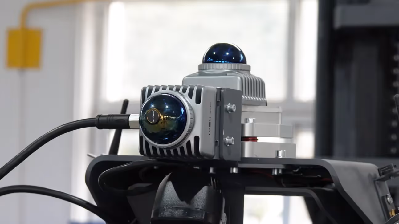
Multi-line LiDAR (e.g. Livox Mid360, Velodyne VLP-16): 3D obstacle avoidance, detects spatial height information to prevent low or overhanging objects.
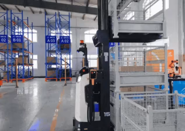
3. Obstacle avoidance radar installation location
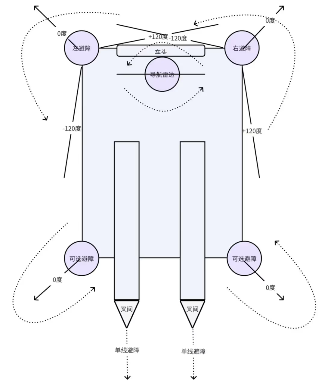
Mainly for the front/rear main obstacle avoidance, lateral protection on both sides of the body, and top global monitoring, as shown in the figure. The front and rear of the vehicle are generally installed on the four corners of the vehicle body, and the radar is tilted outward in front of the radar. Lateral protection on both sides of the body is generally covered by the radar scanning range on the four corners. The top global monitoring systems generally use navigation radar for obstacle avoidance at the same time.
With the radar directly in front as 0 degrees, the range to cover the edge of the body is plus or minus 135 degrees, but due to the body interference, it is necessary to filter out the part close to the body, so the FOV range is generally set to plus or minus 120 degrees. Between the forks generally only detect single line without angle obstacle avoidance.
4. 360-degree spatial surround obstacle avoidance
Need to 2D and 3D radar installation location to ensure that the scanning range of the overall coverage of the body around a circle.
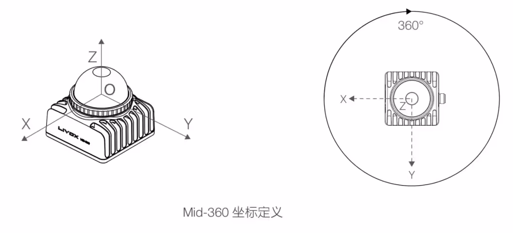
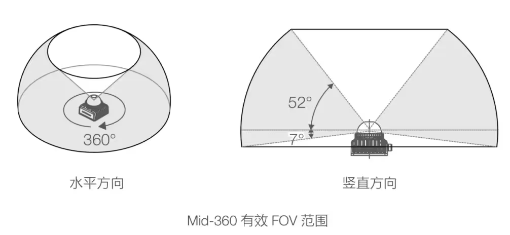
3D radar to mid360 for example, need to know the definition of its coordinates and the maximum coverage of the scanning range, as shown in the figure.
The default scheme is: one 3d radar is installed vertically or upwardly inclined under the front navigation radar, one 3d radar is installed vertically or upwardly inclined on both sides of the body, one 3d radar is installed vertically or upwardly inclined under the forks on the rear side of the body, and the optoelectronic IO is used for obstacle avoidance between the forks.
5. Technical advantages and limitations
Advantage: High accuracy: millimetre-level ranging accuracy, much higher than ultrasonic or infrared. Anti-interference: not affected by ambient light, dust, electromagnetic field (compared to vision sensors). Fast response: scanning frequency usually 10Hz~50Hz, suitable for high-speed AGV (≥1.5m/s).
(4) Laser navigation in handling robots
1. Overview of the principle of laser perception:
After obtaining the point cloud data through 3D radar, it first filters the interference information such as dust and glass reflection, and then extracts the key structural features such as shelf edges, wall corners and pallet fork holes with intelligent algorithms, and finally accurately maps the target objects into the coordinate system, outputs the positional and gestural information and constructs the local environment map with semantics, so as to achieve the intelligent perception of ‘seeing the objects and understanding the scene’. ‘Intelligent perception.
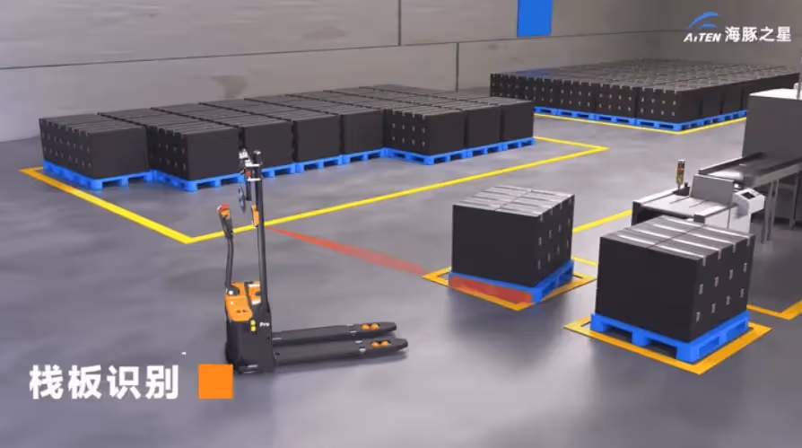
2. Pallet identification and positioning
3. Fork alignment

4. Auto Stacking
5. Technical advantages and limitations
Advantage: High accuracy: Laser ranging accuracy can reach ±1mm, meeting the needs of industrial-grade pallet operation. Resistant to ambient light interference: Compared to vision solutions, laser is not affected by changes in light. Strong real-time: scanning frequency of 10Hz~50Hz, suitable for high-speed logistics scenarios.
Limitations: High cost: LiDAR price is significantly higher than ultrasonic, especially multi-line radar. Special material impact: black light-absorbing objects or specular reflective objects may reduce detection reliability. Computational complexity: real-time point cloud processing requires high computing power (requires embedded GPU or dedicated processor)
Ⅱ. Camera
(1) How ToF uses light waves to achieve millimetre-scale ‘spatial measurement’
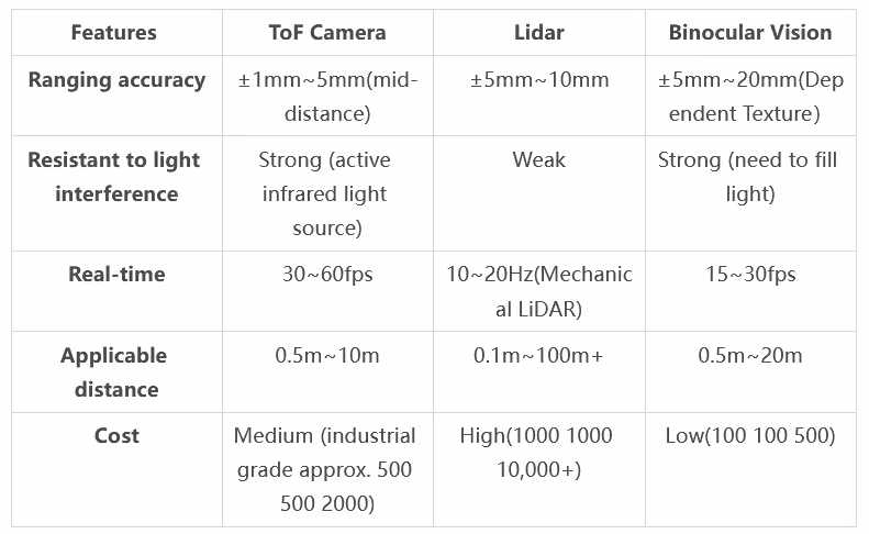
Time-of-Flight (ToF) is one of the three mainstream 3D imaging technologies (the other two being structured light and binocular stereo vision). The principle is to directly obtain the distance information (depth) of an object by emitting near-infrared light and calculating the round-trip time of the light. Compared with other technologies, ToF has the advantages of simple calculation, strong anti-interference, and long-distance measurement, so it is widely used in mobile phone rear cameras (e.g., Huawei/OPPO/Apple), industrial automation, AGV navigation, and robot gripping.
1. dtof
dToF (Direct Time-of-Flight Ranging) consists of three core components:
① VCSEL: emits nanosecond laser pulses;
② SPAD (Single Photon Avalanche Diode): detects reflected light signals at the level of a single photon;
③ TDC (Time-to-Digital Converter): accurately records the round-trip time of the optical pulse.
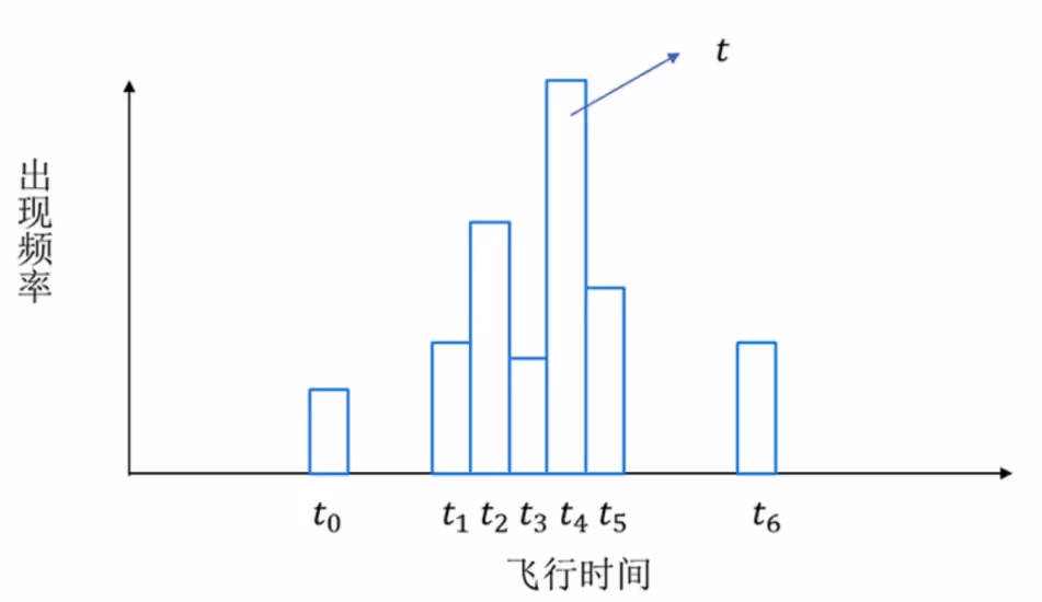
The principle of operation is as follows: transmit and receive N pulses in a single frame, record the time of flight each time through the TDC and generate a histogram, and take the highest frequency time t to calculate the depth (d = ct/2). This technique significantly improves the anti-interference ability through statistical optimisation and achieves high precision depth measurement.
Although the principle of dToF seems to be very simple, it is difficult to achieve a high degree of accuracy. In addition to the very high accuracy requirements for clock synchronisation, there are also high requirements for the accuracy of the pulse signal. Ordinary photodiodes can hardly meet such demands. The core component in dToF, SPAD, is not many manufacturers capable of producing it due to the complexity of the production process, and it is difficult to integrate. Therefore, not many manufacturers are currently researching dToF, and more are researching and promoting iToF.
2. itof
The concept of iToF corresponds to dToF, and the full name is indirect Time-of-Flight, which directly translates to indirect light time-of-flight. By indirect, it means that iToF measures the time-of-flight of light indirectly by measuring the phase shift, instead of measuring the time-of-flight of light directly. iToF transmits modulated infrared light signals into the scene, and then the sensor receives the light signals reflected back from the objects to be measured in the scene, and then calculates the phase difference between the transmitted signal and the received signal based on the accumulated charge during the exposure (integration) time to obtain the depth of the target object. depth of the object. As shown in the figure.
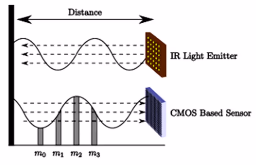
The core components of the iToF module consist of a VCSEL and an image sensor. The VCSEL emits modulated infrared light at a specific frequency. The image sensor receives the reflected light and performs photoelectric conversion during the exposure (integration) time. At the end of the exposure (integration), the data is read out and passed through an analogue-to-digital converter to a calculation unit, which calculates the phase shift of each pixel. iToF calculates the depth using a 4-sampling-bucket algorithm, which utilises 4 samples with phase delays of 0°, 90°, 180° and 270° to calculate the depth. As shown in Fig.

3. Depth map generation
Binocular stereo vision uses the left and right cameras to photograph objects synchronously, and uses parallax (the difference in the position of objects in the image) to calculate the depth, similar to the distance perception of the human eye; while the ToF camera directly records the time-of-flight distance value of each pixel, generating a high-resolution depth map (e.g., 640×480), and combining with the RGB camera to build a colourful 3D point cloud, both of which are the core technologies for 3D environment modelling.
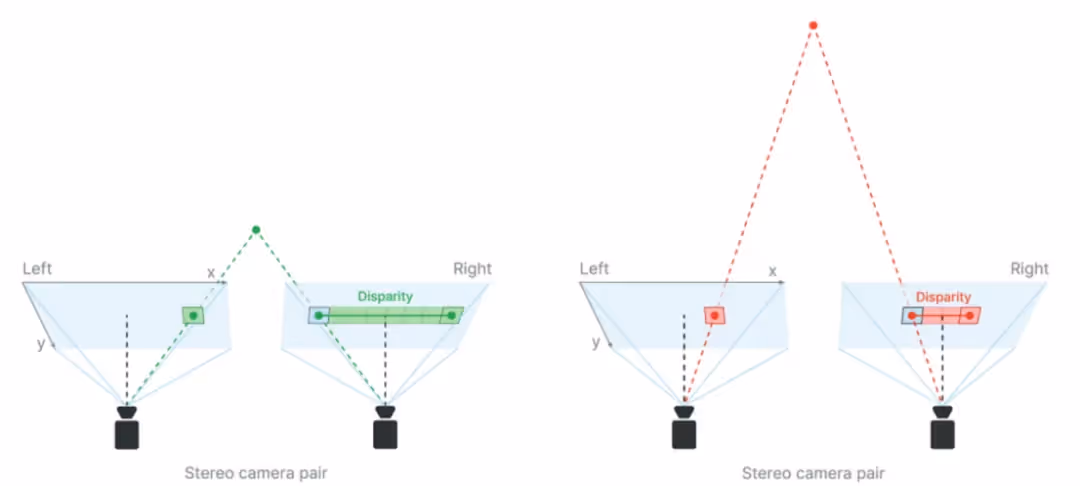
Parallax principle schematic depth map calculation formula:
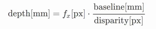
Either a larger baseline distance or a larger focal length will produce deeper depths at the same parallax, which means better depth accuracy. The focal length is the distance between the camera lens and the image sensor. The larger the focal length, the narrower the FOV. Therefore, to obtain long-range depth perception, you can increase the baseline distance and/or decrease the FOV.
(2) Application of the ToF camera in the AGV field
1. Obstacle avoidance and safety protection
Dynamic obstacle avoidance: real-time detection of obstacles within 5m (e.g. people, forklifts, shelves), triggering deceleration or emergency stop. Multi-level safety zone (e.g., warning outside 1m, emergency stop within 0.3m). Low Obstacle Detection: Detect pallets, cargo boxes, etc. on the ground to prevent the AGV from colliding or crushing.
2. Pallet identification and fork picking
Pallet Positioning: Identify the fork hole position of the pallet through depth map, with an accuracy of ±3mm, adapting to different pallet types (wood, plastic, metal). Automatic fork picking: Combined with AGV motion control, the fork arm position is adjusted to ensure accurate insertion.
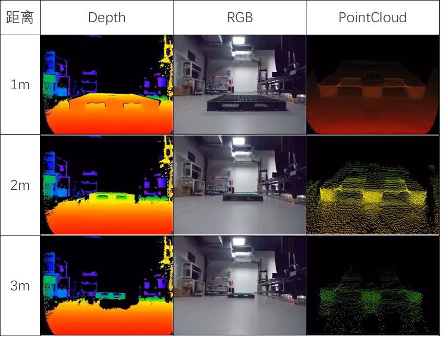
The results of the ToF camera detection of the black pallet are shown in the following figure, depth is the depth map, RGB is the colour map, PointCloud is the point cloud data, the original point cloud is processed through the perception algorithm, and the final output is the two-dimensional position of the pallet relative to the centre of the vehicle body.
Stacking detection: Measurement of cargo height to ensure multi-layer stacking stability.
Volume Measurement: Calculate parcel size (L x W x H) for logistics sorting.
(3) Technical advantages of ToF cameras
Ⅲ. Other Transducers
(1) Ultrasonic Sensor
1. Principle: Transmit a 40kHz-200kHz ultrasonic pulse, receive the reflected signal to calculate the distance.
2. Applications:
AGV obstacle avoidance/in-place detection: typical beam angle 15°~30° (wide distance coverage, low precision);
Transparent object detection (glass/acrylic);
Multiple devices need to prevent crosstalk, and a blind zone (5-20cm) needs to be infrared/laser complementary.
3. Advantages:
Resistant to light/dust/fog interference, adapts to industrial complex environment;
Extremely low cost ($10~100 per unit), long life (>100,000 times);
Non-contact and no wear and tear.
4. Disadvantages:
Low precision (±1~5cm, temperature and humidity influence), needs multi-sensor fusion;
Slow dynamic response (50~100ms), not applicable to high-speed scenes (>1.5m/s);
multipath reflection interference, dependent on algorithms (such as RANSAC), filtering noise
(2) Inertial Measurement Unit (IMU)
1. Principle:
It consists of a gyroscope (measuring angular velocity) and an accelerometer (measuring linear acceleration), with a partially integrated magnetometer to assist in heading calibration;
Output Euler angles through attitude solving and filtering algorithms (e.g. Kalman filtering).
2. Applications:
AGV navigation: fusing encoder data to compensate heading drift and improve positioning accuracy;
Dynamic attitude control: real-time monitoring of fork pitch/roll angle to adjust cargo attitude;
Infrastructure-free positioning: autonomous navigation in tunnels, indoors and other GPS-free scenarios.
3. Advantages:
Fully autonomous, not dependent on external signals (GPS/reflectors);
High-frequency updates (up to 1kHz), real-time;
Resistant to light/dust/electromagnetic interference (except magnetometers).
4. Disadvantages:
Accumulated error: gyroscope drift requires multi-sensor (vision/odometer) fusion correction;
Calibration dependence: stationary calibration of zero bias required at start-up, regular maintenance;
Initial alignment: horizontal static or known attitude initialisation required at start-up
(3) Pull-wire encoder
1. Principle: Displacement measurement through the combination of mechanical transmission and encoder: the pull wire (steel wire/fibre) moves and retracts with the object, driving the internal encoder to rotate and convert the displacement into an electrical signal (formula: displacement = encoder resolution x number of pulses x wheel circumference)
2. Applications: including AGV fork precision control (±1mm accuracy), ramp body levelling and container spreader calibration;
3. Advantages: ultra-high accuracy (±0.01mm), anti-interference (dust/electromagnetic), long travel (up to 50m) and flexible installation;
4. Shortcomings: mechanical wear and tear requires regular maintenance, high-speed movement is easy to jitter (> 1m / s), and only supports unidirectional measurement; multi-degree of freedom requires a combination of multiple devices
(4) Photoelectric distance sensor
1. Principle: emit infrared light and detect the reflected intensity; the closer the distance, the stronger the reflected signal (no precise distance value, only threshold judgement).
2. Application: Generally used for simple obstacle avoidance or in-place detection.
3. Advantages: very low cost. Non-contact measurement: avoid mechanical wear and tear, long life. High-speed response: millisecond detection. Anti-electromagnetic interference: suitable for industrial complex environments.
4. Disadvantages: greatly affected by object colour and surface material. Optical interference: strong light, specular reflection, and transparent objects will affect the accuracy. Ranging range limitations, the general ranging limit value is much lower than the laser
Conclusion
This comprehensive guide explores how cutting-edge sensor technologies enhance the intelligence and agility of AGVs (Automated Guided Vehicles).
Together, these technologies form the sensory foundation for intelligent, responsive, and highly automated material handling solutions.
As an enterprise in the field of intelligent logistics solutions, AiTEN Robotics always focuses on ‘smart factory’ scenarios, deeply integrates technological innovation and industry demand, and has provided comprehensive services for more than 200 manufacturing customers around the world: relying on the full range of handling robot product matrix to cover diverse handling scenarios, self-developed industry-level intelligent scheduling system to achieve efficient collaboration of multiple equipment, and self-developed industry-level intelligent scheduling system to achieve efficient collaboration of multiple equipment. We have provided comprehensive services to more than 200 manufacturing customers around the world: relying on a full range of handling robots to cover diverse handling scenarios, self-developed industry-level intelligent scheduling system to achieve efficient collaboration of multiple devices, and a full life cycle service system covering pre-sales planning, deployment and implementation to operation and maintenance optimisation, we have assisted enterprises in realising the intelligent transformation of logistics and continued to empower the manufacturing industry in digital upgrading and quality development.